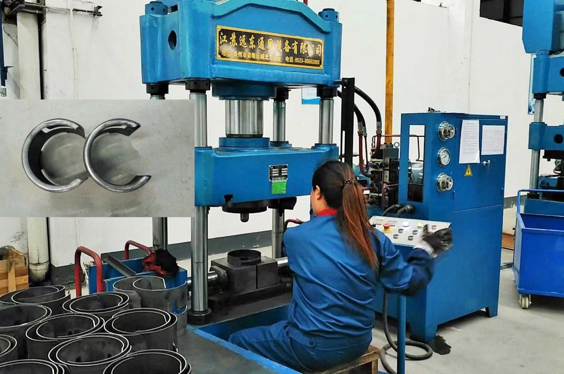
This hydraulic press is a specialized equipment designed for mass and efficient production of LPG cylinder handles. It typically employs hydraulic transmission and mold forming technology, using the punched metal sheet (usually low-carbon steel) through processes such as stretching and bending to form the final shape of the handle in one or multiple pressings.
Equipment Overview and Core Functions
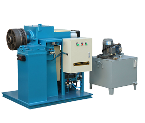
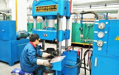
Equipment Name: Liquefied Petroleum Gas Cylinder Handle Forming Hydraulic Press (also known as: Handle Stretching Hydraulic Press, Handle Forming Press)
Core Function: The flat handle blank is formed by cold stamping under high pressure in the mold, resulting in a handle with specific three-dimensional curvature, strength, and dimensions.
Processing Technology: Mainly involves stretching and bending forming.
Features:
4.1 High Efficiency: Automated or semi-automated production, with short single-cycle time and high output.
4.2 High Consistency: The mold ensures the shape, size, and uniformity of each handle.
4.3 Good Rigidity: The equipment structure is sturdy, capable of withstanding uneven eccentric forces, ensuring the forming accuracy.
4.4 Simple Operation: Usually controlled by PLC (Programmable Logic Controller), with a friendly operation interface, requiring only loading and unloading (or automatic completion by a mechanical hand).
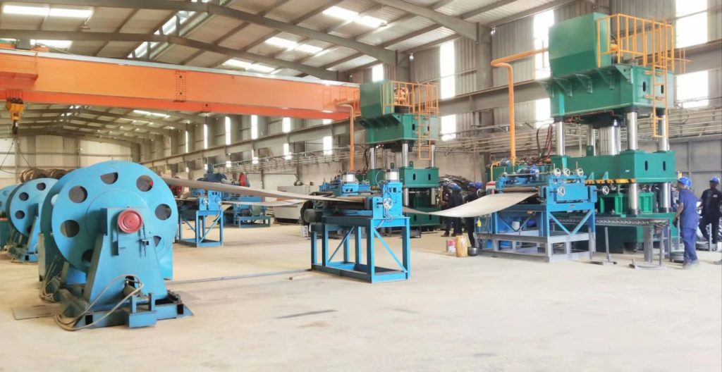
Main Components
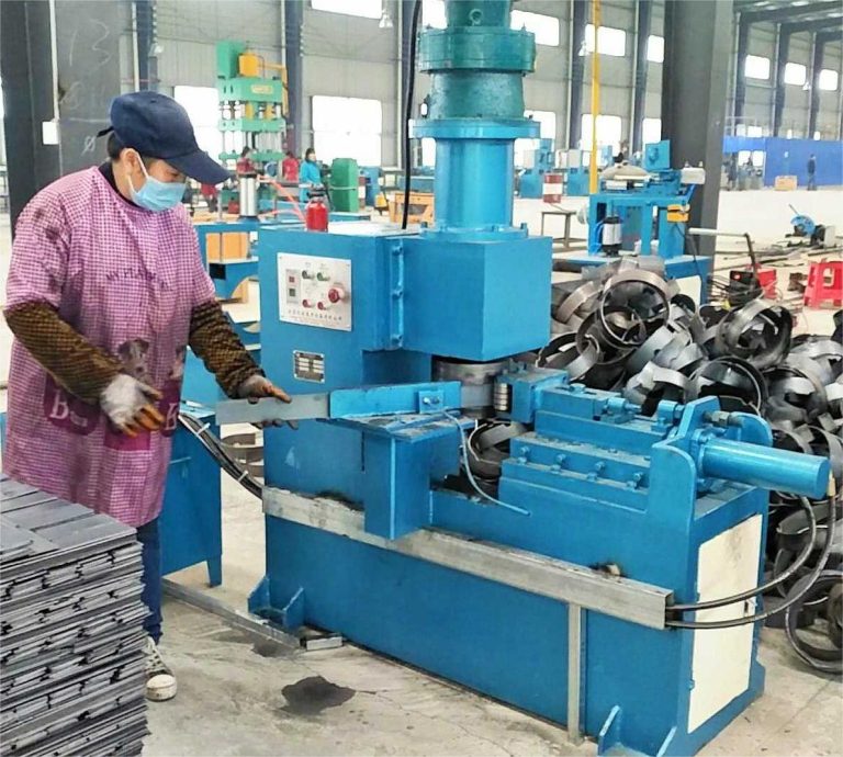
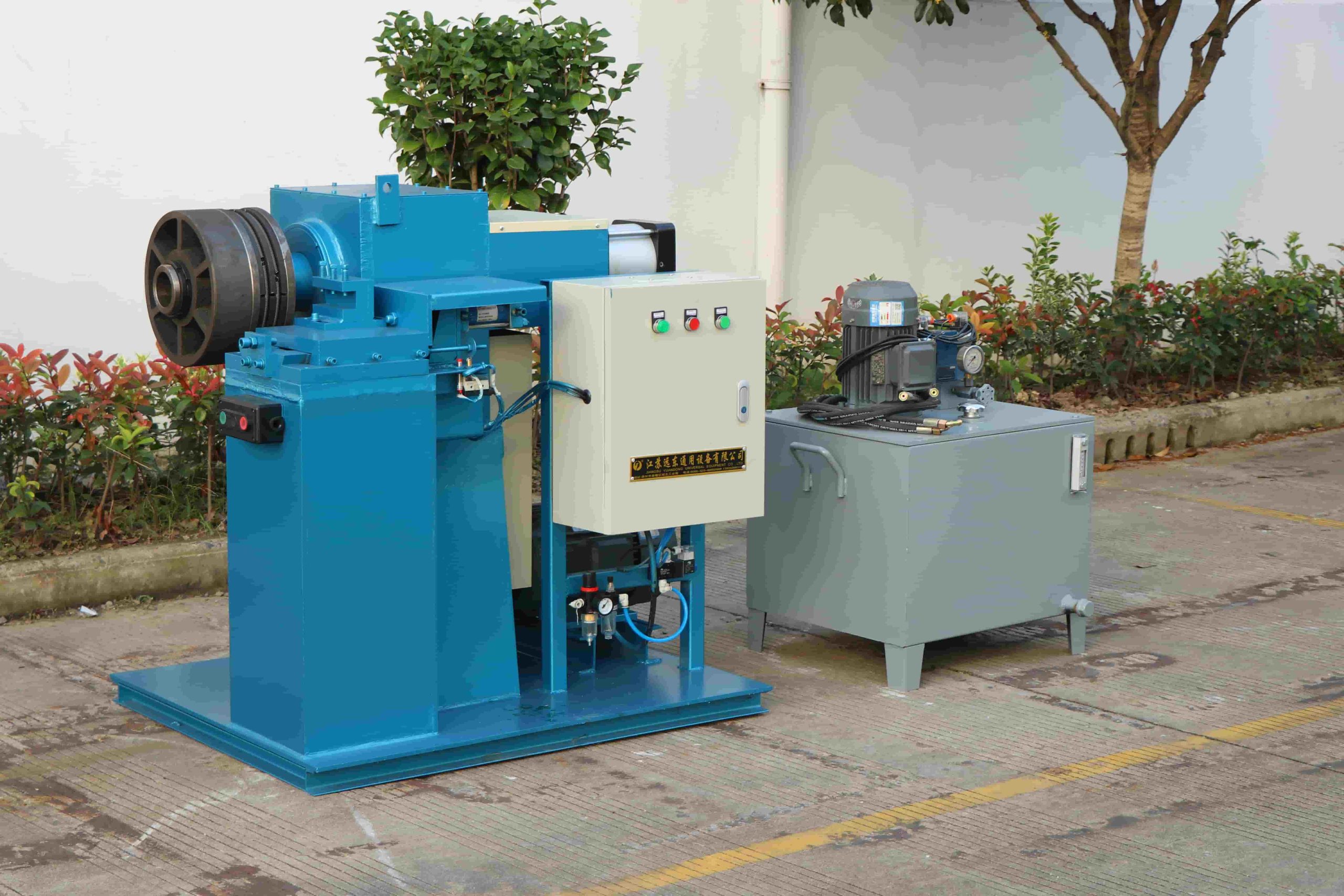
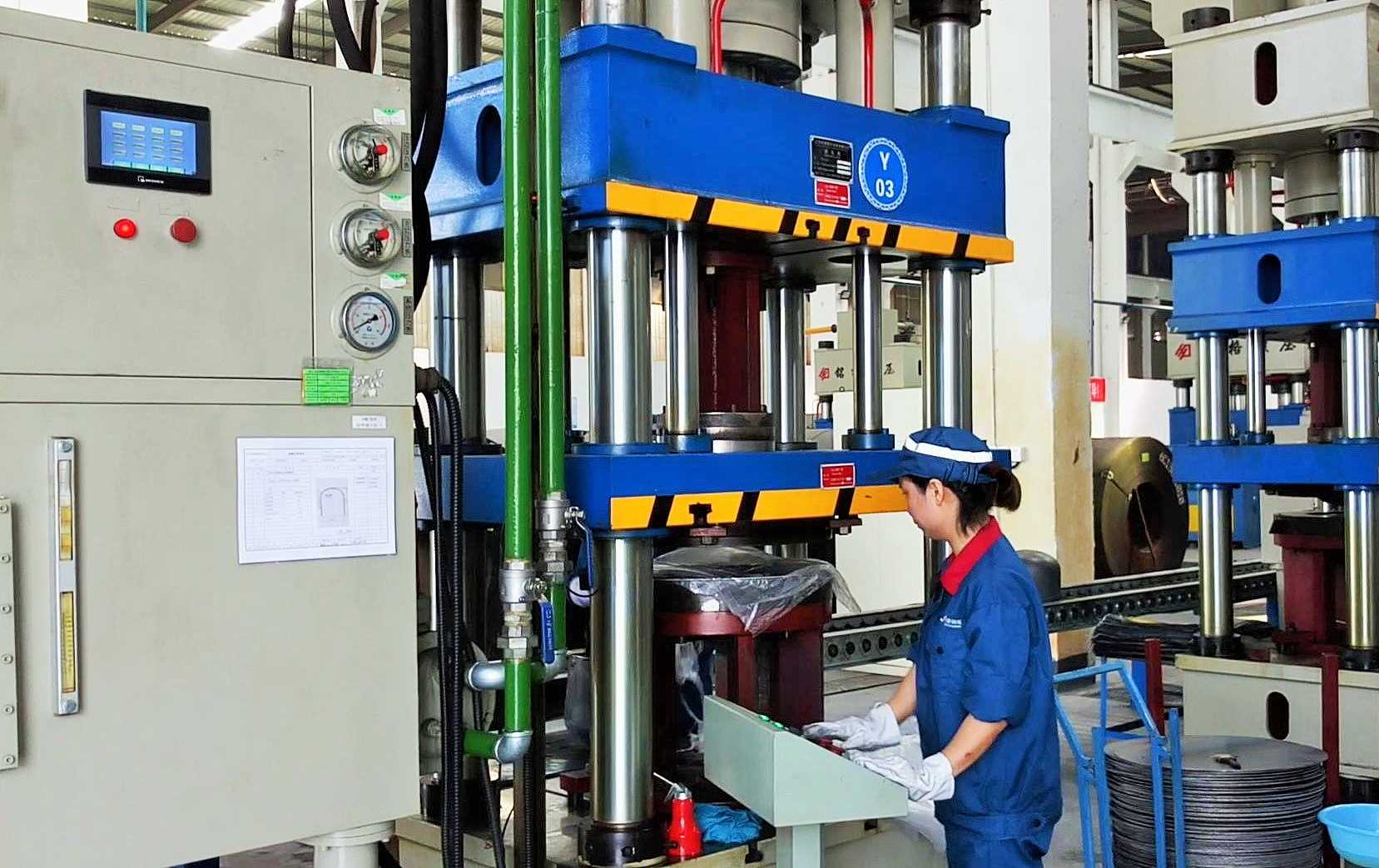
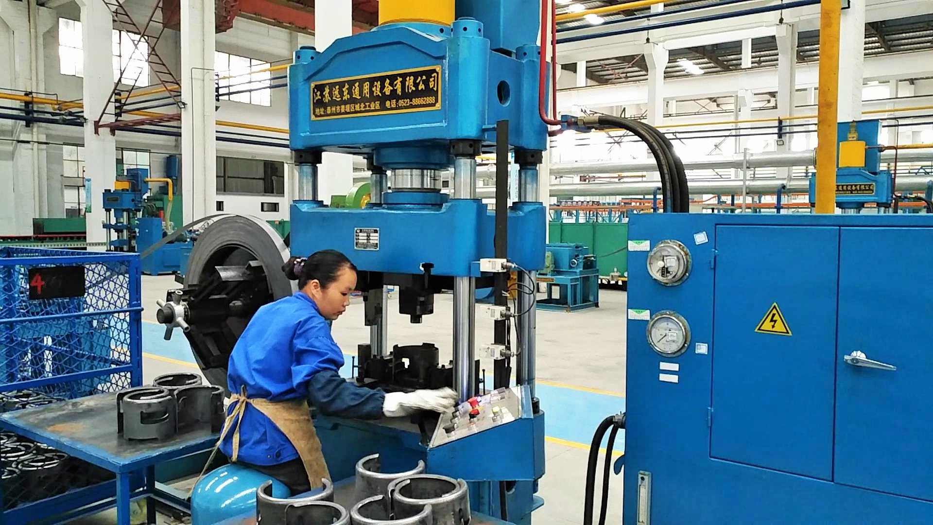
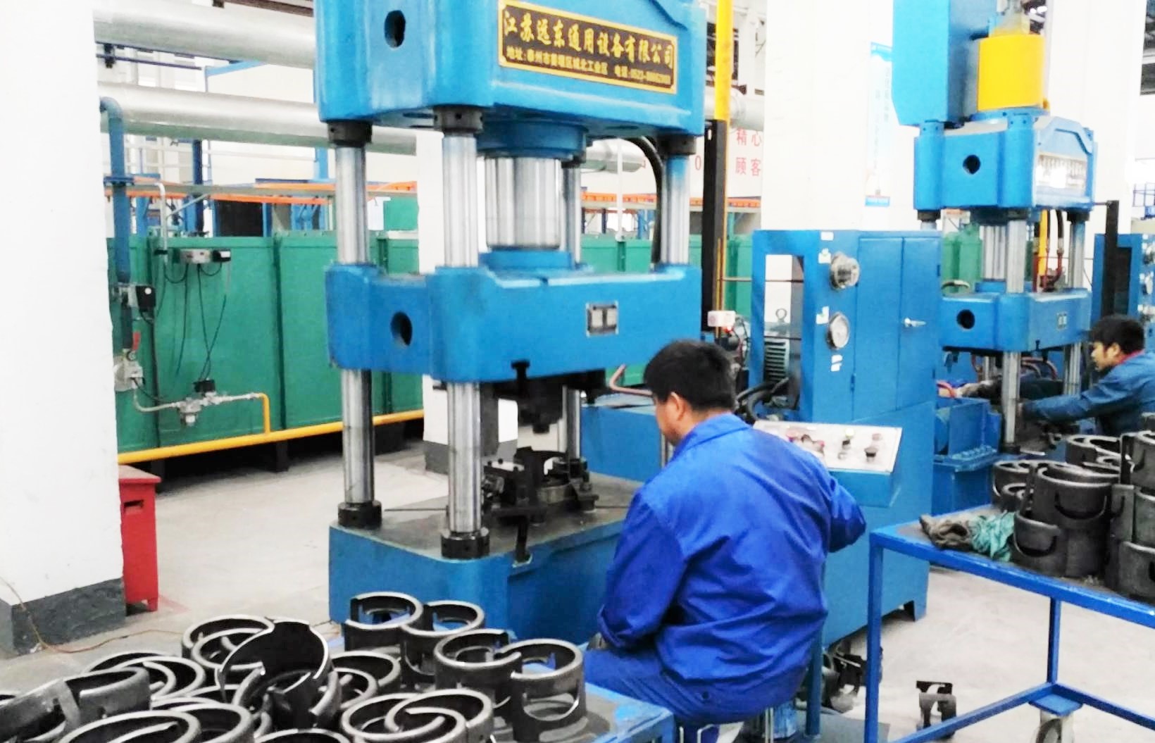
Body (Frame): Usually adopts a three-rod four-column structure or an integral frame structure. It provides a high-strength, high-rigidity enclosed space to withstand the huge pressure during the forming process and ensure the precise alignment of the upper and lower molds.
Hydraulic System: The power core, including:
– Motor and oil pump: Provide stable high-pressure hydraulic oil.
– Hydraulic cylinders: As the actuating mechanism, driving the moving crossbeam (slider) to move up and down, providing the pressure required for the forming.
– Control valve group: Including directional valves, pressure valves, and flow valves, controlling the sequence, pressure, and speed of the hydraulic cylinders.
– Oil tank, piping, and cooling system: Ensure the circulation and heat dissipation of the hydraulic oil.
Electrical Control System: The control brain, usually with PLC (Programmable Logic Controller) as the core, combined with a touch screen (HMI). It is used to set and adjust parameters such as pressure, stroke, and holding time, and control the automated operation of the entire working cycle.
Mold: The key to forming, including the upper mold (installed on the moving crossbeam) and the lower mold (installed on the worktable). The shape of the mold cavity directly determines the final shape of the handle. The mold design needs to consider material flow, exhaust, and demolding.
Auxiliary Devices (optional): Automatic feeding machine, automatically transporting the blank to the mold center position.
– Mechanical hand/robot: Automatically pick up and place the workpiece, achieving fully automated production.
– Safety light curtain/both-hand buttons: Ensure the safety of the operator.
III. Typical Working Process (semi-automatic example)
Preparation: The operator places the punched handle blank on the positioning device of the lower mold.
Start: Press the double-hand start button, and the hydraulic press begins the working cycle.
Rapid descent and pressure application: The moving crossbeam descends rapidly, approaches the blank, then slows down and applies the set pressure to the blank for pressing.
Holding pressure: Under maximum pressure, the moving crossbeam remains for a short period (holding pressure), allowing the material to undergo sufficient plastic deformation, stabilizing the forming, and reducing rebound.
Pressure release and return: The holding pressure ends, the main cylinder releases pressure, and the moving crossbeam rises back to the original position.
Retrieval: The operator (or the mechanical hand) retrieves the formed handle from the lower mold, completing one working cycle.
Key Technical Parameters
| Parameter Type | Explanation | Typical Range (Reference) |
| Nominal Pressure | Maximum output force generated by the hydraulic mechanism | 100 – 500 tons (commonly 200 – 315 tons)
|
| Workbench Size | Available area for installing the mold | Dependent on the size of the mold and the product, e.g. 1000mm x 1000mm
|
| Slider Travel Distance | Maximum moving distance of the movable crossbeam | 300 – 600 mm |
| Opening Height | Maximum distance from the workbench surface to the lower plane of the movable crossbeam | 600 – 1200 mm |
| System Working Pressure | Rated pressure of the hydraulic system | 25 – 31.5 MPa |
| Operating Speed | Quick descent, feed, and return speeds of the slider | Effects production efficiency, adjustable |
Summary of Advantages
Specialization: Specifically designed for the forming of handles for liquefied petroleum gas cylinders, with high compatibility of the process.
High Efficiency: Far surpasses the production speed of traditional friction presses or manual forging.
High Quality: The formed parts have clear contours, smooth surfaces, high strength, and low springback.
Energy Conservation and Environmental Protection: Compared to old equipment, it has lower energy consumption and lower noise.
Great Automation Potential: Easy to integrate into automated production lines, reducing the need for manual labor.